
A 6-prong ignition switch is common on many older cars, lawn tractors, ATVs, generators and custom projects. It lets you control multiple circuits (battery, ignition, starter, accessories, dash lights, and sometimes a secondary ignition feed) from one keyed switch.
Below is a clear, practical explanation of each terminal, a typical wiring map, step-by-step hookup instructions, safety notes, and troubleshooting tips so you can wire one confidently.
6 Prong Ignition Switch Wiring Diagram
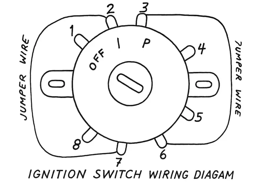
Manufacturers don’t all use the same labels, but most 6-prong switches contain the following terminals:
- BATT (Battery / B) — constant 12V input (hot). Supplies power to the switch.
- IGN (Ignition / IGN1) — main switched 12V that powers the ignition system, fuel pump, ECU, etc.
- START (S or ST) — momentary output to the starter solenoid; energized only while cranking.
- ACC (Accessory / A) — switched 12V for radios, cigarette lighter, accessories active in the “ACC” position.
- IGN2 (IG2 / IGN R) — secondary ignition or switched output for things that should only be powered in the RUN position (fans, some modules).
- ILLUM / L (Lights / Lamp) — power for dash illumination or key illumination; sometimes used for illumination negative/positive depending on design.
Important: terminal names and pin order differ between manufacturers. Treat this as a typical layout, always confirm with the specific switch’s datasheet or the vehicle wiring diagram.
Related Are Lawn Mower Ignition Coils Interchangeable?(Find Out)
Typical wiring color map (common convention)
Wire colors vary by vehicle. Below is a common convention used in many aftermarket and OEM harnesses. Use it as a guideline, not gospel:
- BATT (Red) – constant 12V from battery (through a fuse).
- IGN / IGN1 (Yellow) – switched feed to ignition coil / ECU.
- START (Green) – momentary feed to starter solenoid.
- ACC (Brown or Tan) – accessories.
- IGN2 (Orange or Purple) – secondary ignition feed or switched power for pumps/cooling.
- ILLUM (Blue) – dash/key illumination lamp.
Simple textual wiring diagram
Connect as follows for a standard install:
- Battery + → BATT (Red) on switch (via a fuse or fusible link).
- IGN (Yellow) → vehicle ignition feed (coil, ECU, ignition module).
- IGN2 (Orange) → additional switched circuit (fuel pump relay, fan relay, etc.).
- ACC (Brown) → accessories (radio, lighter) that should work in ACC or RUN.
- START (Green) → starter solenoid S terminal (only active while key is cranking).
- ILLUM (Blue) → dash/key illumination (or to lamp circuit if required).
Related Briggs and Stratton Ignition Coil Resistance Chart
Step-by-step hookup
- Disconnect the battery negative before you touch anything. Safety first.
- Identify each terminal on your new switch (look for small stamped letters: B, I, S, A, L, IG2). If letters aren’t present, consult the seller’s diagram or datasheet.
- Run a fused 12V lead from the battery positive to the BATT terminal. Use the appropriate fuse rating (typically 10–30A depending on expected load).
- Connect IGN to the ignition feed harness. Use ring/crimp terminals and heat shrink.
- Connect START to the starter solenoid trigger wire. Ensure this wire is isolated from accessories to avoid powering the starter inadvertently.
- Connect ACC to the accessory circuit (radio, etc.).
- Connect IGN2 where you need a run-only switched feed (if not needed, you can cap and insulate this wire).
- Connect ILLUM to the dash illumination circuit (or cap if not used).
- Recheck all connections, reattach the battery negative, and test positions: OFF → ACC → RUN → START.
Related Ignition Coil Resistance Chart(For All Brands/Engine Types)
Safety & best practices
- Use a fused battery feed — failure to fuse the BATT lead risks fire.
- Use proper crimping or soldering and heat-shrink for reliable connections.
- Keep starter (S) wire insulated and away from accidental grounding. The starter engages with a momentary contact; never wire it to be continuously hot.
- If unsure about color coding or pinout, use a multimeter to verify continuity and switched outputs across key positions before making final connections.
- When working on modern vehicles, check for immobilizers or BCM (body control module) dependencies, simply wiring a switch may not start a car with electronic security.
Troubleshooting quicklist
- Key in RUN, but engine dies: check IGN and IGN2 feeds; verify fuses and relays.
- Accessories work, but the engine won’t crank: verify START wire and starter solenoid; check battery voltage under load.
- Switch fuses blow immediately: probable short to ground on one of the switched outputs, disconnect outputs, and test individually.
- Illumination doesn’t work: confirm ILLUM polarity and that dashboard lamps expect ground-switching vs. positive switching (some vehicles switch the ground side).
Related Craftsman LT2000 Drive Belt Diagram(Fixed)
FAQs
What color wires go to the ignition switch?
Typically, Red goes to the battery (BATT), Yellow to ignition (IGN), Green to the starter (START), Brown to accessories (ACC), Orange or Purple to secondary ignition (IGN2), and Blue to illumination (L). However, colors can vary by manufacturer, so always confirm before wiring.
How does a 6 prong switch work?
A 6-prong ignition switch works by routing power from the BATT terminal to different circuits, ignition, starter, accessories, depending on the key position (OFF, ACC, RUN, START). It controls multiple electrical systems from one key rotation.
What is L1 and L2 on a light switch wiring diagram?
L1 and L2 usually refer to line and load terminals on a light switch. L1 often connects to the live (power) input, while L2 connects to the output going to the light fixture. In ignition switches, these may correspond to lighting or accessory outputs.
What does R1 and R2 mean on an ignition switch?
R1 and R2 terminals typically represent secondary ignition outputs or “run” circuits. They supply power to systems that operate only when the key is in the RUN position, such as the fuel pump or electronic control units.
What is the color code for the switch wires?
Common ignition switch color codes are:
- Red: Battery
- Yellow: Ignition
- Green: Starter
- Brown: Accessory
- Orange/Purple: Secondary ignition
- Blue: Illumination
These colors may differ between manufacturers, so checking your specific wiring diagram is essential.
How do you check ignition wires?
Use a digital multimeter to test continuity and voltage:
- Turn the key to the desired position (RUN or START).
- Measure the voltage from each terminal to ground.
- BATT should always read 12V.
- IGN and ACC should read 12V in RUN.
- START should read 12V only while cranking.
- If any terminal doesn’t behave as expected, inspect the wiring or the switch for faults.
Final words
A 6-prong ignition switch offers clean control over multiple circuits, but variations in pin labels and wiring colors mean the golden rule is to verify before connecting.
When in doubt, consult the switch’s datasheet, the vehicle’s wiring diagram, or use a meter to identify which terminal changes state as you turn the key. If you’re uncomfortable around starters or the main battery feed, consider having a certified mechanic or auto electrician double-check your work.